Rotor bars skewing is commonly used in the induction motor design to reduce the torque ripple, minimize the cogging effect and improve the machine performance. In general, 2D FEM is not able to take into account rotor bars skewing and proper modeling of the skewed rotor bars requires 3D simulations. As an alternative to lengthy 3D FEM simulations multi-slice FEM is often used.
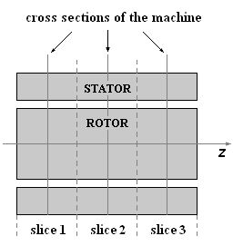
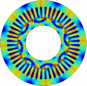
The idea of multi-slice FEM consists in dividing the machine along the z-coordinate into several slices. The cross section geometry changes from one slice to another according to applied rotor bar skewing. Then the magnetic field problem is solved in every slice all at the same time with 2D FEM together with circuit equations of the stator and rotor windings.
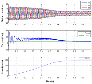
In this example the induction motor with a rotor bar skew angle of 8 degrees is simulated with multi-slice FEM using different number of slices. Simulation results are compared in order to determine the optimal number of slices to obtain the desired accuracy. When only one slice is used, the induction motor with unskewed rotor bars is basically simulated. The following pictures compare the torque and current waveforms for different number of slices.
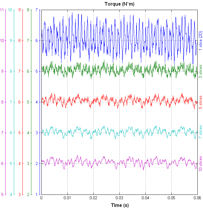
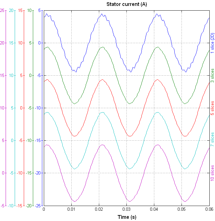
Even with three slices used the torque ripple is significantly reduced and the current waveform becomes much smoother. Simulation results are compared in the following table:
| Number of slices | Torque (N*m) | Torque ripple (%) | RMS current (A) | Speed (rad/s) |
|---|---|---|---|---|
| 1 | 6.05 | 27.9 | 3.010 | 146.44 |
| 3 | 6.05 | 10.2 | 3.015 | 146.27 |
| 5 | 6.05 | 8.7 | 3.016 | 146.25 |
| 7 | 6.05 | 8.3 | 3.017 | 146.25 |
| 10 | 6.05 | 8.0 | 3.017 | 146.24 |